CMoy (25) So far...
This is the schematics of my 4ch-buffered-CMOY headphone amplifier. My DIY headphone amp started from a pure CMOY with OPA2134, and then after additional buffers and channels were added not solely logically, but under existing physical constraints. So, this schematics also reflect those constraints and signs of try and error.
General configuration:
- IC1 and IC2 are for L/R channels.
- IC3-1/2 and IC4 are for GND channel for amplifire circuit.
- IC3-2/2 and IC5 are for GND channel for output.
- Input AC coupling caps are eliminated.
Some details:
- Supply caps are increased to 1500uF each, from 220uF each in original CMOY. This is to ensure driving low impedance earphones with enough bass response, together with 10ohms resistors at L/R output.
- IC1 and IC2 are connected in series, not in A47 connection. This is because I had tried single Tr emitter follower buffer for IC2 position. It can be like A47.
- 22pF for IC1 feedback loop is for stable behavior of LT1469-2. 22pF is not needed if you use OPA211 or OPA637 for IC1.
- IC3-1/2 and IC4 are connected oddly, and it is because of installation reason. My original intention was to use single opamp for Ch3. I tried additional buffer for Ch3 by stacking buffer-opamp on top of the original opamp IC. See below pictures. These can (or should) be simpler series connection or A47. Or single amp from AD8397 may be enough as buffer, I suppose.
- 20pF for IC3-2/2 feedback loop is for stable behavior of LT1469+LT1010. Thru my trial, as long as you want to use opamp IC or LT1010 as buffer for output GND, IC3-2/2 shall not be faster than LT1469 or OPA627. Too fast opamp, like AD8397 or LT1394, may cause heavy oscillation of buffer IC, IC5. An output resistor outside the loop, such like appeared at L/R channel amps, may work to avoid oscillation, though, I do not want to introduce such common impedance for L and R.
- Electrolytic cap at LT1010 bias pin is from a figure on LT1010 datasheet. In addition, I install another electrolytic across +V and -V pins of LT1010, also from datasheet. See below picture.

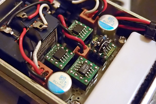
AD8397 stacked as IC4. In this picture, AD8397(IC4) is stacked on OPA211(IC3). LT1469 is for IC1, two AD8397s are for IC2 and IC5. AD8397 works quite well as IC5, more stable than LT1010. Good thing of LT1010 is its 'Air' in sound, I think. OPA211 as IC3 also works fine, but LT1469 gives cleaner bass sound.

Configuration in this picture is identical to the schematics above. Two small electrolytics are for LT1010, 15uF for biasing pin, 100uF for +V/-V. Two MAHA 300mAh are connected in parallel. Mini-jack at the side of the amp is for charging the batteries. Current consumption is around 70mA with this configuration, resulting around 8hrs battery life.
Bottom line:

So far, combination of LT1469(-2) + LT1010 or AD8397 is quite good for my preference. It is clean and with air, but still keeping passion of music. It is wide and flat, but still with solidness of each sound. I am thinking my next DIY amp with higher supply voltage with similar opamps as above, expecting what I experienced with Portaphile V2^2 + 18V Supply.
All of my subjective impressions above are from my favorite phones, ATH-ESW10JPN, HD650, SE530, UM2, AH-C700 and ER-4S. My source device is iPod nano 3rd.
